ROOF-2 8x6m (TAF)
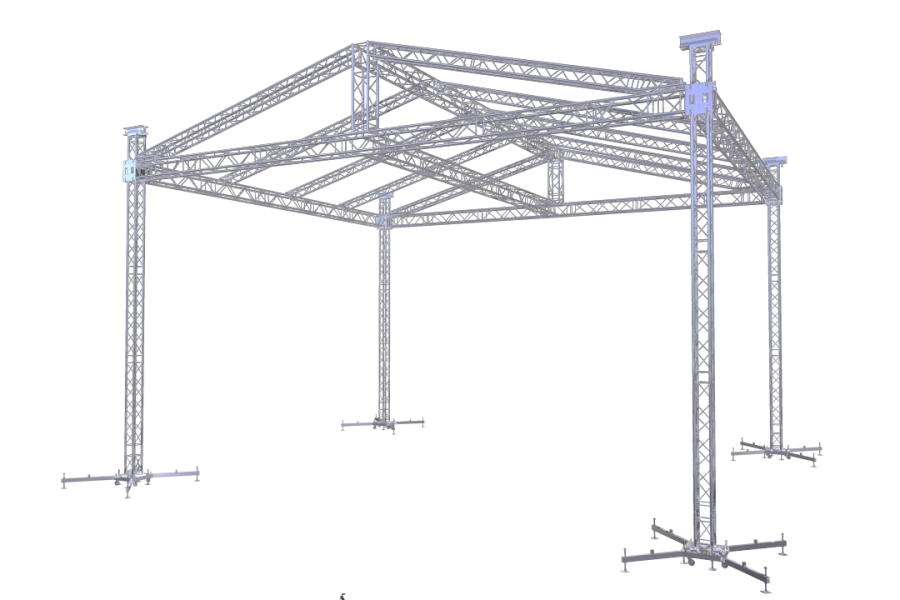
Roof 2 - pitched roof structure with great design. Covering stage 8 x 6 m
Technical Specification
Gable roof design has become the standard in aluminum truss temporary roof structures throughout the world. Roof 2 system comes in three different size variations covering small to big size events. It is a very popular roof structure thanks to its variability, strength and decent size measures. The main grid is assembled on the ground and then lifted up thanks to the employment of Tower 1 elevation systems.
The main rectangular grid of Roof 2 is made of FT44 trusses while the front and rear rafters come from FT34 truss line and the inside rafters are made by FT33 truss segments. The gable of the roof is created by the FT34 rafters and specifically designed corners for strong and secure roof structure attachment. The inside FT33 rafters are connected to the main grid and top beam through clamps. The rafters are spaced 2 m apart from each other in order to create a sufficient support for the top canopy placement eliminating water pockets.
Roof 2 for stage size 8 x 6 m (26 ft x 19.5 ft) maybe smaller in size but its loading characteristics are quite high. Front and rear main beams of the grid can carry load up to 150 kg/m (101 lb/ft) and at the same tim the side truss beams can handle imposed load of max. 100 kg/m (67 lb/ft). In total the max. loading capacity of the roof comes up to 3500 kg (7716 lb). he operational wind limit for using the roof system with the side canopies on all three sides is 20 m/s (45 mph).
| SPECIFICATIONS | |
Max. dimensions | 10,5x8,5 m |
Max. stage size | 8x6 m |
Max. clearance | 7 m |
Max. height | 8,57 m |
Max. load bearing capacity | 3500 kg |
Total weight of construction | 2000 kg |
LOADING CAPACITY | |
Max.Load Bearing Capacity | 3500 kg |
Front Horizontal Beam | 150 kg/m |
Rear Horizontal Beam | 150 kg/m |
Side Horizontal Beams | 100 kg/m |
DOWNLOAD
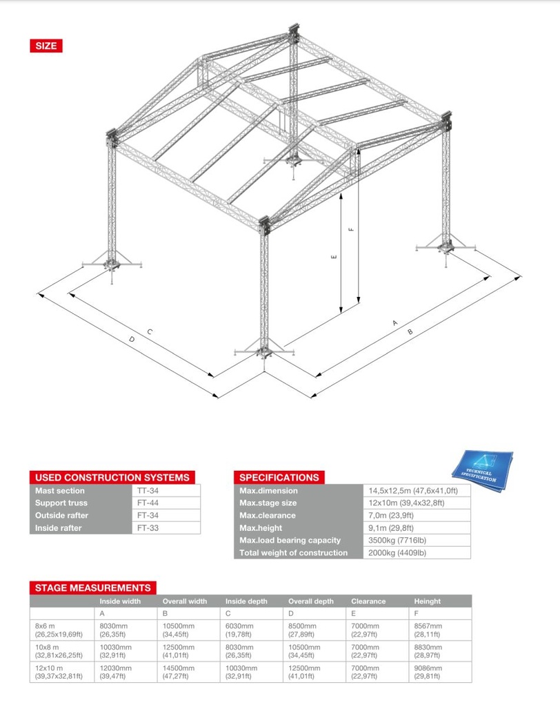
ROOF DIMENSIONS | | |
Stage size | 8000x6000 mm | |
Inside width | A | 8030 mm |
Overall width | B | 10500 mm |
Inside depth | C | 6030 mm |
Owerall depth | D | 8500 mm |
Clearance | E | 7000 mm |
Height | F | 8567 mm |
Used Truss
Main Grid
FT44 truss - box truss with 400 x 400 mm (16 in x 16 in) outside dimensions, main pipe Ø 50 x 2 mm (2 in x 0.08 in), braces Ø 25 x 3 mm (1 in x 0.12 in). The alloy used as material for the pipes is EN AW-6082 T6.
Rafters
FT34 truss - box truss with 290 x 290 mm ( 12 in x 12 in) outside dimensions, main pipe Ø 50 x 2 mm (2 in x 0.08 in), braces Ø Ø 20 x 2 mm (0.8 in x 0.08 in). The alloy used as material for the pipes is EN AW-6082 T6.
FT33 truss- triangle truss with 290 x 258 mm (12 in x 10.15 in) outside dimensions, main pipe Ø 50 x 2 mm (2 in x 0.08 in), braces Ø 20 x 2 mm (0.8 in x 0.08 in). The alloy used as material for the pipes is EN AW-6082 T6.
Columns
Tower 1 - TT44 truss, steel base plate, long outriggers, top section and sleeve block
Wind Management
Wind resistence is calculated with 3 side mesh canopies applied to the structure (2 side canopies and one rear canopy). The three roof walls carrying canopies must be secured by guy wire cross bracing at all times as well as the top grid horizontal ceiling.
Side walls guy wires min. loading capacity - 2500 kg (5512 lb)
Rear walls guy wires min. loading capacity - 2700 kg (5953 lb)
Roof ceiling guy wires min. loading capacity - 1000 kg (2205 lb)
Please note that tension capacity of guy wires needs to be higher than required min. loading capacity.
In service max. allowed windspeed - 20 m/s - 72 km/h - 45 mph
Ballast
Option 1 - 2100 kg / 4630 lb ballast underneath each tower base = total of 8400 kg / 18,519 lb ballast necessary
Canopy and Side Walls
Top canopy is available standardly in silver grey and black color. The material used is SIO-LINE B 8000 with weight of 630 g/m2.
The side walls are covered by air permeable mesh canopies in black.
Transportation Data
Total weight: ca. 2000 kg ( 4409 lb)
Transport volume:
All truss segments are packed in brown carton boxes for better handling and protection during transport.
